How it Works
Structure and calculation principles of NozzlePy
NozzlePy consists of two main modules: Contour Calculation and Contour Optimization.
The pre-filled example parameters correspond to representative values of the Aerojet Rocketdyne RS-25 rocket engine.
Contour Calculation
The Contour Calculation module can be used for both the Contour Generation and Efficiency Evaluation of the respective Nozzle Contour.
Contour Generation
The Contour Generation function is used to calculate the Nozzle Wall Geometry for a given set of Parameters.
The Geometry calculation methods included in NozzlePy are: Ideal Nozzle, Truncated Ideal Contour (TIC) and Thrust
Optimized Parabola (TOP).
The created contour is displayed on the right plot window and can be exported as a .dxf file for implementation
into CAD programs.
Ideal Nozzle
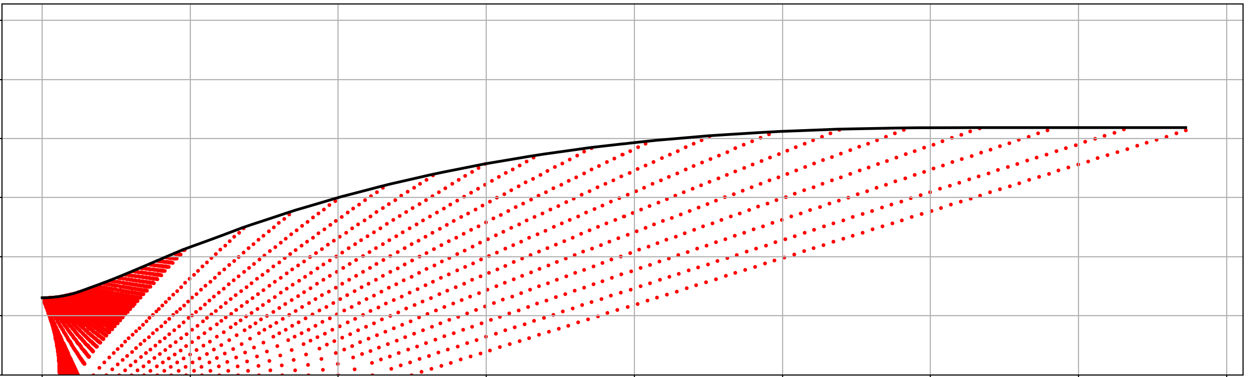
The Ideal Nozzle contour is calculated using the Method of Characteristics (MoC).
The main contour defining parameter for the Ideal Nozzle method is the exit Mach number.
An initial parabola is applied at the Nozzle Throat according to Sauer's method, where the
initial flow Mach number is set to 1.1. From here on the Characteristic lines, emitted from the
supersonic flow, are traced and a linearized approximation to the real flow properties is calculated
with a Euler-method error correction for accuracy.
The initial expansion contour is chosen to be a circular arc with a user-set radius. Calculating the
Characteristic points downstream of the initial parabola, once the user-set exit Mach Number at the Nozzle
main Axis (y=0) is reached, the circular arc has reached its maximum wall angle.
For the Ideal Nozzle Contour, the flow at the Nozzle exit is shock-free, parallel and uniform. Therefore, the turning
contour of the nozzle is calculated via mass flow balance across each characteristic line.
The Method of Characteristics not only yields the ideal De-Laval Nozzle Contour, but also offers a solution of the supersonic flow
at each Characteristic point (marked as the red points in the graphic below).
The corresponding flow properties throughout the nozzle: Velocity, Pressure, Temperature, Density can be investigated via the Plot settings.
Required Parameters:
- Resolution of Characteristic Mesh
- Desired Exit Mach Number
- Initial Mach Number (= 1.1)
- Combustion Chamber Pressure
- Ambient Pressure
- Combustion Chamber Temperature
- Isentropic Exponent of Exhaust Gas
- Specific Gas Constant
- Nozzle Throat Radius
Truncated Ideal Nozzle (TIC)
The Truncate Ideal Contour, or TIC is derived from the Ideal Nozzle solution.
The full-length ideal contour is truncated at a user-defined geometric Boundary.
The truncation parameters can be set to:
(Max Relative Nozzle Length, Max absolute Nozzle Length, Max absolute Nozzle Width, Expansion Ratio or Nozzle exit Angle).
In addition, by selecting both the Max absolute Nozzle Length and Max absolute Nozzle Width, a Geometric Envelope can be set, which defines
the maximum Nozzle Size.
In addition, the TIC Method offers the inclusion of boundary layer calculations. These base on the Laminar
Blasius' Boundary Layer solution, which uses the Local Reynolds number, Flow Velocity and Density to calculate the Flow Shear Force at the
Nozzle Wall. The Reynolds number is calculated via local distance from Nozzle exit, local flow velocity and local kinematic viscosity.
The Viscosity on the other hand is calculated through the three parameters Sutherland Constant , Reference Dynamic Viscosity and Reference Temperature. Typical values
for these parameters can be obtained from the following table:
| Gas | Reference Dynamic Viscosity μ₀ [Pa·s] | Reference Temperature T₀ [K] | Sutherland Constant Sμ [K] |
|---|---|---|---|
| Air | 1.716 × 10⁻⁵ | 273 | 111 |
| Argon | 2.125 × 10⁻⁵ | 273 | 114 |
| CO₂ | 1.370 × 10⁻⁵ | 273 | 222 |
| CO | 1.657 × 10⁻⁵ | 273 | 136 |
| N₂ | 1.663 × 10⁻⁵ | 273 | 107 |
| O₂ | 1.919 × 10⁻⁵ | 273 | 139 |
| H₂ | 8.411 × 10⁻⁶ | 273 | 97 |
| Steam | 1.12 × 10⁻⁵ | 350 | 1064 |
The Boundary Layer Calculation additionally yields the displacement thickness, which is used to calculate the final Nozzle Contour Geometry.
Required Parameters:
- All parameters from Ideal Nozzle
- Truncation Criterion
- Reference Dynamic Viscosity
- Sutherland Constant

Thrust Optimized Parabola (TOP)
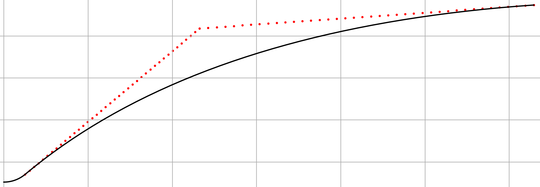
The Thrust Optimized Parabola (TOP) contour is generated by appending a quadratic Bezier curve to an initial
circular arc. The defining Parameters for the contour are the maximum wall angle, which defines its positional
vector through the circular arc, the exit wall angle and the exit Mach number of the flow. The positional vector
of the exit point is calculated via isentropic calculations for the Expansion Ratio, as well as the corresponding
length of a 80% Conical Nozzle, which determines the TOP Nozzle Length.
The results of the standard TOP method do not yield any information about the flow field and therefore the Nozzle efficiency.
By selecting the -Include Flowfield Calculation- Button, it is possible to run a complete characteristic mesh calculation with the
pre-calculated TOP contour. Instead of the massflow comparision used for the Ideal Nozzle, the parabola is used as a boundary condition.
SINCE THE TOP CONTOUR EXPANDS THE FLOW NON-IDEALLY, THE OCCURING SHOCK WAVES (which can be seen in the characteristic mesh) CAN DISRUPT
THE LINEARIZATION PROCESS OF THE MOC. UNCERTAINTIES MAY OCCUR DUE TO THIS PROBLEM.
The TOP Contour Generation also includes a Boundary Layer Calculation, similar to the TIC Nozzle.
- All parameters from Ideal Nozzle
- Max. Wall Angle
- Exit Wall Angle
- Reference Dynamic Viscosity
- Sutherland Constant
Efficiency Evaluation
Since the complete flow field of both the TIC and TOP Nozzle is calculated, the efficiency of the nozzle can be calculated. This
is done by first identifying the characteristic points at the Nozzle exit and interpolating the Flow Velocity and massflow to the
Nozzle exit plane. After Integration, the Thrust and therefore the specific Impulse Isp and Thrust Coefficient Cf are calculated.
The Efficiency Calculation gives the divergence loss, boundary layer loss (if included by user) and overall performance of the TIC and TOP Nozzle.
This Data can be exported as a .txt file.

Contour Optimization
The Contour Optimization module determines optimal geometric parameters for TIC and TOP nozzles under physical and geometric constraints.
TIC Optimization
The TIC optimization determines the optimal exit Mach number and relative truncation length of a TIC Nozzle in order to maximize the thrust coefficient Cf for a given set of combustion and flow conditions. These flow conditions are set in the Contour Calculation module. It employs an adaptive, resolution-refining search algorithm to efficiently locate the global maximum while minimizing computational effort. If selected by the user, the optimization additionally includes Boundary Layer effects, evaluates the Summerfield criterion (P_exit / P_ambient = 0.4) for flow separation detection at the Nozzle exit and applies Geometric Boundary Conditions.
TOP Optimization
The TOP optimization varies the maximum wall angle, exit angle, and exit Mach number to identify the optimal TOP contour. A nested, adaptive parameter sweep refines the design space locally to achieve high accuracy while maintaining computational efficiency, with the supersonic flow field resolved via the method of characteristics. Again, Boundary Layer Effects, Summerfield Criterion and Geometric Boundary Conditions can be included.
Program Operation
It is possible to save the parameters, set by the user for Contour Calculations via File -> Save or Save As... These .json files can similarly be loaded into your Project via File -> Load...
NozzlePy Documentation
A detailed mathematical derivation of the Method of Characteristics, efficiency models and optimization procedures used in NozzlePy is provided in the following technical document.